Visual Representation of Cellular Processes: Animal Cell Coloring Labeled And Colored

Animal cell coloring labeled and colored – Visualizing cellular processes is crucial for understanding the intricate workings of a cell. Detailed diagrams, employing color-coding and precise labeling, can effectively communicate complex mechanisms and molecular interactions. This section will explore the visual representation of several key cellular processes.
Endocytosis
Endocytosis, the process by which cells absorb external material, can be visually represented in several stages. Imagine a cell membrane, depicted as a flexible, wavy blue line. A small, reddish-brown vesicle containing extracellular material approaches the membrane. The membrane then begins to invaginate, or fold inward, around the vesicle, shown as a deepening indentation in the blue line.
This indentation progresses, forming a pocket that completely encloses the vesicle. Finally, the membrane pinches off, creating a newly formed, smaller vesicle containing the extracellular material now fully inside the cell, depicted as a small, separated reddish-brown circle within the cell’s cytoplasm. The entire process should clearly illustrate the membrane’s dynamic nature and the formation of the endocytic vesicle.
Cellular Respiration
Cellular respiration, the process of energy production within mitochondria, can be effectively visualized by illustrating the movement of molecules within the mitochondrion. Represent the mitochondrion as a double-membrane structure: an outer, smooth, gray oval encompassing an inner, folded, darker gray oval. The folds, or cristae, should be clearly indicated. The process can be shown as a flow chart, with glucose molecules (represented in yellow) entering the mitochondrion.
These glucose molecules are then broken down through glycolysis (depicted with small yellow arrows), followed by the Krebs cycle (depicted with orange arrows) within the mitochondrial matrix (the space within the inner membrane). Finally, the electron transport chain (depicted with purple arrows) on the cristae generates ATP (represented as green circles), the cell’s energy currency. The movement of electrons and protons should be indicated with arrows, highlighting their role in ATP synthesis.
Protein Transport
Illustrating protein transport within the cell requires showing the movement of proteins from ribosomes to their final destinations. Begin by showing a ribosome (represented as a dark purple sphere) attached to the endoplasmic reticulum (ER), a network of interconnected membranes depicted as a light blue network. As the ribosome synthesizes a protein (a light green strand), the protein enters the lumen of the ER.
The protein then travels through the ER, indicated by the light green strand moving along the light blue network. Next, the protein moves to the Golgi apparatus (a stack of flattened sacs, depicted in light orange), where it undergoes modification and packaging. This is shown as the protein strand transitioning from light green to a darker green, indicating modification.
Finally, the modified protein is transported in a vesicle (a small, dark green circle) to its final destination, whether it’s the cell membrane, lysosome, or other organelle. The path of the protein should be clearly traced, highlighting the key organelles involved.
Mitosis
Mitosis, the process of cell division, can be effectively illustrated using a series of labeled diagrams, each showing a key stage. Use different colors to represent the chromosomes. For example, use red for one set of chromosomes and blue for the other. Prophase: Depict the chromosomes condensing and becoming visible, each consisting of two sister chromatids (represented by the duplicated red and blue structures joined at the centromere, a constricted region).
The nuclear envelope begins to break down. Metaphase: Show the chromosomes aligning along the metaphase plate (an imaginary plane in the center of the cell) which should be indicated by a dotted line. Each chromosome’s centromere is attached to spindle fibers (represented as light gray lines). Anaphase: Illustrate the sister chromatids separating and moving to opposite poles of the cell.
The red and blue chromatids now move independently towards opposite sides of the cell. Telophase: Show the chromosomes reaching the poles, decondensing, and the nuclear envelope reforming around each set of chromosomes. Two distinct nuclei are now visible. Finally, cytokinesis, the division of the cytoplasm, results in two daughter cells, each with a complete set of chromosomes.
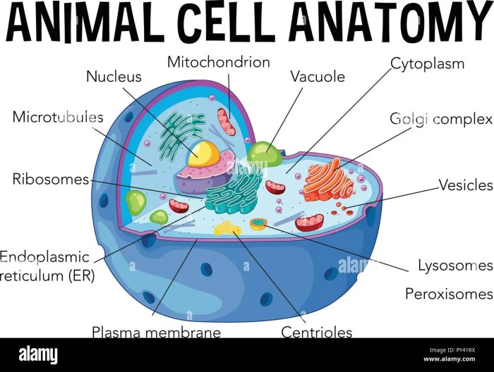
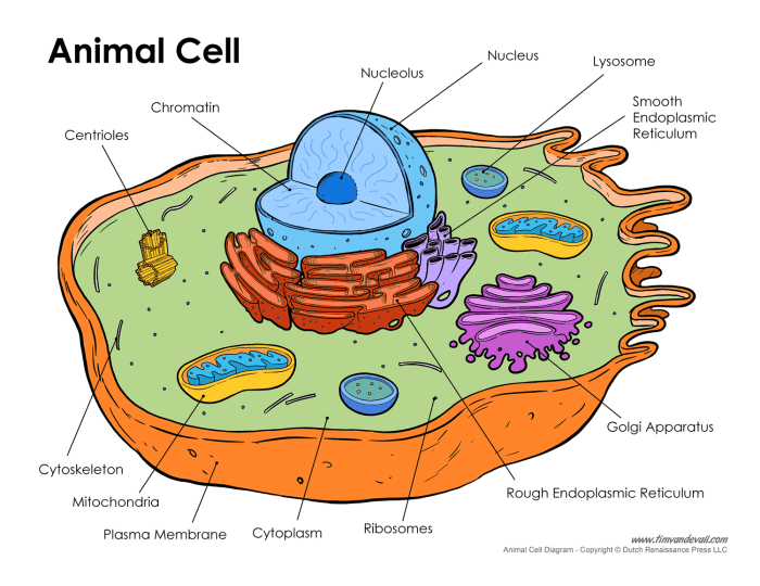
Creating a labeled and colored animal cell diagram is a great way to visualize its components. Understanding the intricacies of animal cells often leads to a broader interest in cell biology, prompting exploration of other cell types. For a comprehensive comparison, you might find the resource on animal and plant cell diagram coloring helpful. Returning to animal cells, remember to accurately label key organelles like the nucleus and mitochondria when completing your coloring exercise.
Microscopic Observation and Interpretation

Microscopic examination is crucial for understanding the structure and function of animal cells. Prepared slides allow for detailed observation of cellular components, revealing features invisible to the naked eye. By comparing observations across various microscopic techniques, a more complete picture of cellular organization emerges.Observing Key Features Under a Light MicroscopeA light microscope reveals several key features in a prepared slide of animal cells.
The cell membrane, a thin outer boundary, is usually visible as a distinct line delineating the cell’s perimeter. The nucleus, typically a large, round or oval structure, is readily identifiable due to its prominent size and often darker staining compared to the surrounding cytoplasm. Within the cytoplasm, the granular appearance often indicates the presence of numerous ribosomes and other organelles, although individual organelles like mitochondria or the endoplasmic reticulum may not be clearly resolved at this magnification.
The overall shape and size of the cells, and any visible inclusions or vacuoles, can also provide valuable information about the cell type and its state.
Comparing Microscopic Techniques
Different microscopic techniques offer varying levels of detail and reveal different aspects of cellular structure. Light microscopy provides a general overview of cell morphology and the location of major organelles. However, resolving smaller organelles requires higher magnification and resolution offered by techniques such as electron microscopy. Transmission electron microscopy (TEM) provides high-resolution images of internal cellular structures, revealing the detailed morphology of organelles like mitochondria, endoplasmic reticulum, and Golgi apparatus.
Scanning electron microscopy (SEM) provides three-dimensional surface views of cells, highlighting surface features and textures. For instance, the detailed cristae within mitochondria are only visible using TEM, while the overall shape and surface projections of a cell are best visualized with SEM. Fluorescence microscopy allows visualization of specific cellular components using fluorescently labeled antibodies or dyes. This technique can be used to identify the location and distribution of specific proteins or organelles within the cell.
Interpreting Microscopic Images
Interpreting a microscopic image involves systematic analysis of the visual information. Begin by identifying the overall cell shape and size. Then, locate the key organelles: the nucleus, cytoplasm, and cell membrane. Observe the distribution and arrangement of other visible structures, noting their size, shape, and staining characteristics. The presence of inclusions, such as lipid droplets or glycogen granules, can also provide insights into the cell’s metabolic activity.
The clarity of the image, the presence of artifacts, and the staining technique used should all be considered when interpreting the image. For example, the presence of numerous dark-staining granules might suggest a high concentration of ribosomes, indicating high protein synthesis activity.
Creating a Labeled Diagram, Animal cell coloring labeled and colored
Consider a hypothetical microscopic image of a fibroblast cell viewed under a light microscope at 400x magnification. The cell is roughly 20 µm in length and 10 µm in width, exhibiting a typical elongated shape. The nucleus, measuring approximately 5 µm in diameter, is centrally located and stains darkly. The cytoplasm appears relatively clear with scattered dark granules (ribosomes), indicating active protein synthesis.
The cell membrane is visible as a thin, dark line surrounding the cell. A small vacuole, about 2 µm in diameter, is observed near the cell periphery. A labeled diagram would clearly show these structures with corresponding measurements and descriptions. For example, the label “Nucleus (5 µm diameter)” would be positioned next to the depicted nucleus. Similarly, labels and measurements would be included for the other identified structures.
Clarifying Questions
What software is best for creating labeled and colored animal cell diagrams?
Several programs work well, including Adobe Illustrator, BioRender, and even Microsoft PowerPoint. The best choice depends on your skill level and access to software.
How important is accuracy in the size and placement of organelles in the diagram?
Accuracy is crucial for avoiding misconceptions. While perfect scale isn’t always achievable, relative sizes and locations of organelles should be represented as realistically as possible.
What are some common mistakes to avoid when creating these diagrams?
Common mistakes include inconsistent labeling, inaccurate representation of organelle size and location, and using colors that don’t clearly differentiate organelles.
Are there any online resources beyond software for creating these diagrams?
Yes, many websites offer pre-made templates or resources to assist in creating your diagrams. Searching for “animal cell diagram templates” will yield numerous results.


